-
 Máy gia công CNC
-
Máy cắt dây / Máy xung
-
Máy tiện vạn năng
-
Máy phay vạn năng
-
Máy tiện, máy phay mini
-
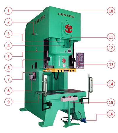
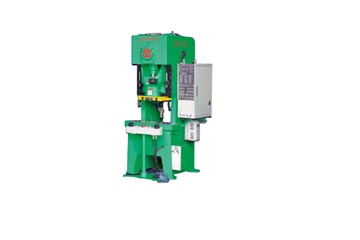
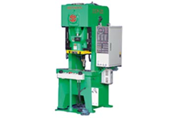
Máy gia công tôn
-
Máy cắt CNC
-
Máy cơ khí khác
-
Phụ kiện gá kẹp Hàn Quốc
-
Thiết bị đo, hiệu chuẩn
-
Dụng cụ cắt gọt
-
Dụng cụ đo Insize
-
Dụng cụ đo Mitutoyo
-
Dụng cụ Vertex
-
Dụng cụ cầm tay
-
Thiết bị hàn cắt
-
Thiết bị dạy nghề
-
Phụ kiện VERTEX
-
Dịch vụ
Phòng KD :
0942 03 08 86


0915 115 185
0948 255 266
Phòng dự án :
0902 299 389
0983 69 2797